This document explains extinction ratio in a simplified way. This is one of the most important parameters in optical transmitters used in high-speed digital communication and video systems. It ensures that optical transmitters maintain a specific performance level. This parameter is used to describe how efficiently the electrical power is converted to optical power.
More importantly, Extinction ratio (ER) is the key parameter to describe the performance of an optical transmitter for the SDI video world. For all the parameters of SDI optical signal, please refer to the ST297-2015.
Extinction ratio references the difference between the energy of the positive level (transmitted 1) and the negative level (transmitted 0). The greater the ratio is, the wider the separation. The optical receiver, similar to electrical, must decide if the signal is a ‘1’ or a ‘0’. Using this analogy, if you are at a rock concert and the background noise is high, you will have trouble to hear your friend speaking close to you. Because the singer has a better ratio or level, you will hear the song more clearly than your friends voice.
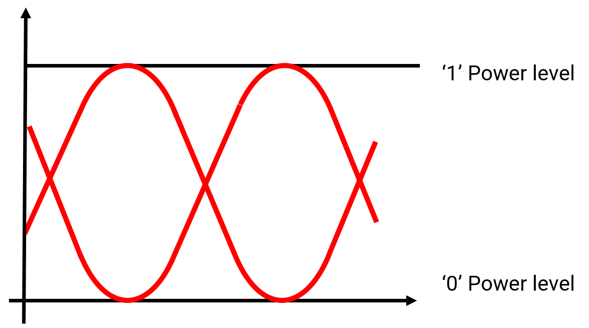
Figure 1. Definition of extinction ratio (Drawing available from: http://www.embrionix.com)
This analogy is not only for the ER, but on the signal that will travel over fiber with attenuation and noise. In other words, the wider the separation between the 1 and the 0, the more robust your system is.
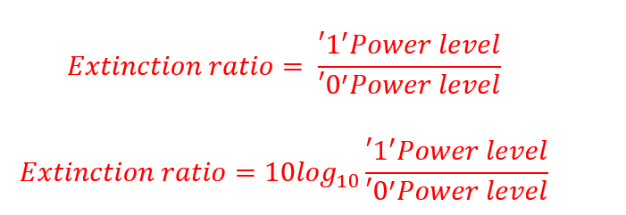
Thus, if the ‘1’ power level is 1000 microwatts, and the ‘0’ power level is 50 microwatts, the extinction ratio will be 13dB.
You might wonder why ‘0’ power level should not be targeted for improvement. The reason is a physical one. As a second analogy, when you turn on your incandescent bulb (I know it is old tech…) there is a delay between the light passing from ‘off’ state (‘0’ power level) to ‘on’ state (‘1’ power level). This is intrinsic to today’s laser. The laser should remain in the ‘on’ state, but with the lower ‘0’ level. This ensures a better ER, and more robust system.
The crucial parameter when you study the system performance is the bit-error-ratio (BER), which represent how many bits will be transported without a single error. This is a measure of system stability and reliable fiber path. In theory, any well-designed communication/video system is error free if you have a transmitter with high ER, and if you have an ideal system path. No fiber run, no passive device in the path, no splices or connectors, etc.
In a real life application, when a communication or video system is designed, architects should take note of the factors which attenuate and add noise to their system. Finally, lengthening the transmission span will degrade the system BER, as signal level drops and noise increases.
However, as mentioned with the analogy of the singer in the concert, transmitter extinction ratio will impact the length of transmission distance and robustness of such system.
There is a mathematical expression to calculate the ER versus power penalty, but allow me to summarize it with a table.
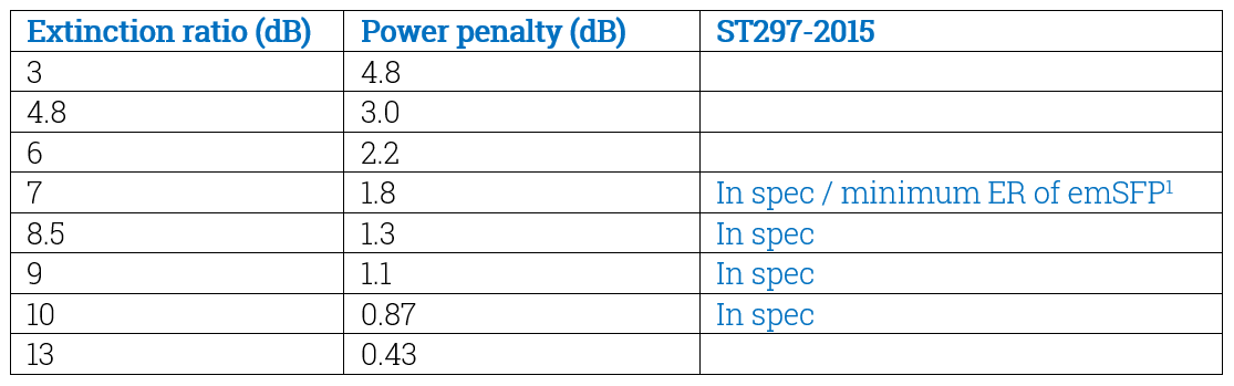
Note: if you are calculating the architecture of communication / video systems, remove this power penalty from your budget. Be aware that an ER lower than 4.8 reduces your power by more than half!
Note: Our new generation of EB12LCRT and EB12LC2T has an ER between 7dB and 10dB at 11.88Gbps, which gives a fiber distance of 40km at 11.88Gbps.
Seemingly small changes in ER will make significant difference in the power required to maintain a good BER. This effect is especially noted when ER < 7dB; a change from 7dB to 3dB will cut your power budget in half. Architects and designers should be aware that the extinction ratio has a big impact on their customer’s system.
Embrionix emSFP are carefully designed to ensure the ST297-2015 ER is met over the entire temperature range.
For more information about our products. Please contact us at Embrionix_Sales@riedel.net
About Embrionix
Embrionix, a subsidiary of Riedel Communications, designs and builds innovative, advanced SMPTE video SFPs to close the gap between fiber optic deployments, coaxial deployments, legacy composite deployments, and emerging technologies, such SDI to IP SFPs. By leveraging its core competencies in video broadcast, the company OEMs highly flexible SFP modules (emSFP) to major manufacturers in the industry. Embrionix headquarters are based in Laval, Quebec. Embrionix sales offices, representatives, and distribution offices are located in Canada, United States, United Kingdom, Germany, France, and Japan.
About Riedel Communications
Riedel Communications designs, manufactures, and distributes pioneering real-time video, audio, data, and communications networks for broadcast, pro audio, event, sports, theater, and security applications. The company also provides rental services for radio and intercom systems, event IT solutions, fiber backbones, and wireless signal transmission systems that scale easily for events of any size, anywhere in the world. Riedel is headquartered in Wuppertal, Germany, and employs over 700 people in 25 locations throughout Europe, Australia, Asia, and the Americas.
All trademarks appearing herein are the property of their respective owners.