This document explains the difference between transparent clock and boundary clock. It also explains that Boundary clock could scale easily compared to transparent clock. The first section is the definition of the precision time protocol (PTP) functionality, ST 2059-1 and ST 2059-2, transparent clock and boundary clock definition. The next section shows the IP broadcast center clocking scheme and which PTP clocking is better.
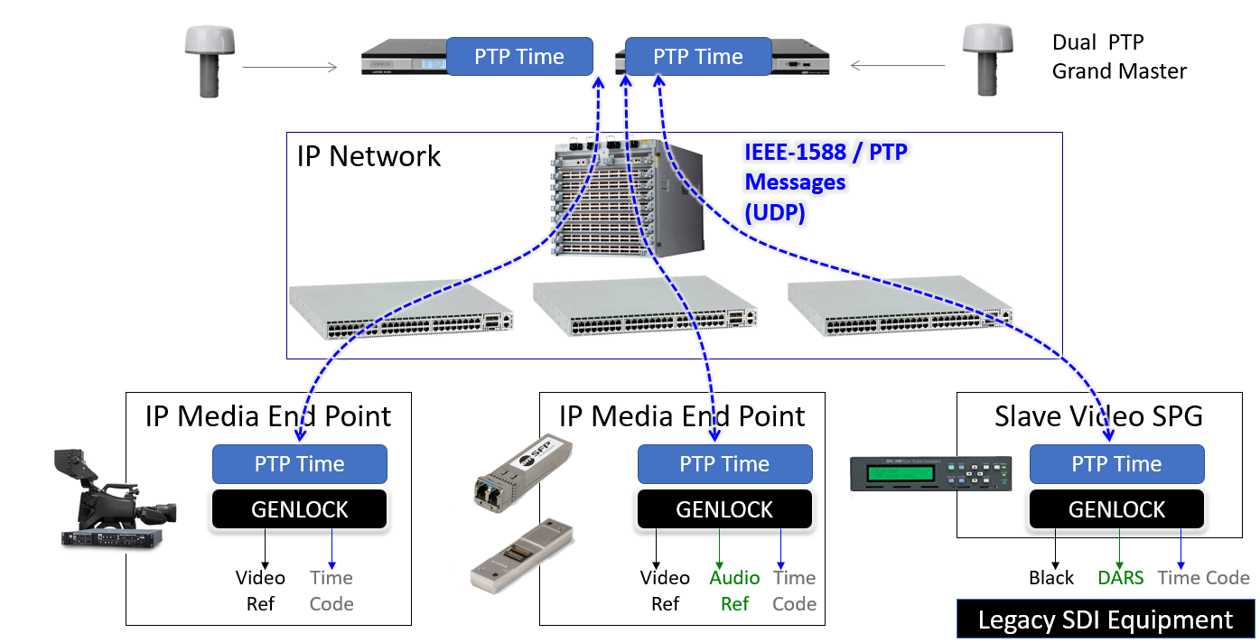
Figure 1. Video and Time Reference in an IP Media Facility (courtesy of Michel Proulx)
The PTP is defined by the specification IEEE-1588. It is an algorithm that synchronizes the peripherals on the network with a common time reference. Before
PTP, there was the network time protocol (NTP) which allowed systems to be synchronized within a few milliseconds of coordinated universal time (UTC). While the provided precision proved to be enough for basic transfer of time of day information, it is not enough for real-time applications such as audio and video. To improve accuracy, thus
enabling real-time applications to utilize the Ethernet network, the Institute of Electrical and Electronics Engineers (IEEE) defined PTP.
The method is simple. A high precision clock, the Time Transmitter, will send out PTP sync messages using the User Datagram Protocol (UDP). Time Receiver will then receive the sync messages with the Time Transmitter time (t1). If hardware timestamping is not provided by the Time Transmitter, a Follow_Up message will be sent out to provide the time at which the initial sync message was sent out (t1). The Time Receiver stores the time at which it receives the Sync message (t2). After reception of the Sync message, the Time Receiver sends out a Delay_Request to the Time Transmitter clock (t3). The Time Transmitter finally answers with a Delay_Response message (t4).
Having these four timestamps, the Time Receiver device can estimate the propagation delay and calculate its own offset from the Time Transmitter. The following formulas are used in the Time Receiver to establish the time at the Time Transmitter:
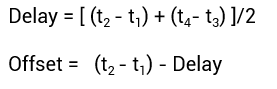
Equation 1: PTP Delay and Offset calculation
The following image shows the low-level PTP algorithm
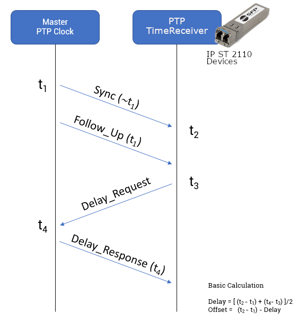
Figure 2: PTP Algorithm (courtesy of Embrionix design)
The transparent clock will relay the Time Transmitter’s PTP Sync, Follow_Up and Delay_Resp messages to all of the Embrionix’s IP SFPs
and will transfer PTP Request_Delay messages from all the SFPs to its Time Transmitter. The PTP Time Transmitter usually can answer to a limited number of Time Receivers. When this number becomes too large, the Time Transmitter starts to be over solicited by the
number of messages.
The network gets more congested, and packet scheduling across the network can add delays, which in turn cause ina
ccuracy in time synchronization (PTP messages have different delays that are not compensated for). The transparent clock adjusts the PTP messages to remove the delays of its own packet processing, and thus compensates delays in PTP messaging.
In a spine-leaf architecture, as defined in our recent presentation: ( https://www.embrionix.com/resource/IP_Television_infrastructure_emMODULAR_emSFP_gateway ), the top of rack switches can adjust the delay inside the PTP packets (by adding a correction field in PTP message) to ensure it is viewed as transparently as possible.
![]()
Figure 3. Transparent clock system (courtesy of Michel Proulx)
The boundary clock ready switches possess a built-in PTP Time Transmitter clock. The switch will be the Time Transmitter for the endpoint devices attached to it. For stability, the switch will be a Time Receiver to another PTP Time Transmitter clock. In this scenario, the PTP Time Transmitter in the switch will communicate to a limited number of Time Receivers. This way the boundary clock method ensures that PTP Time Transmitters are not over solicited, and this will greatly improve the accuracy of the PTP time and the system scalability. The following picture shows a boundary clock system.
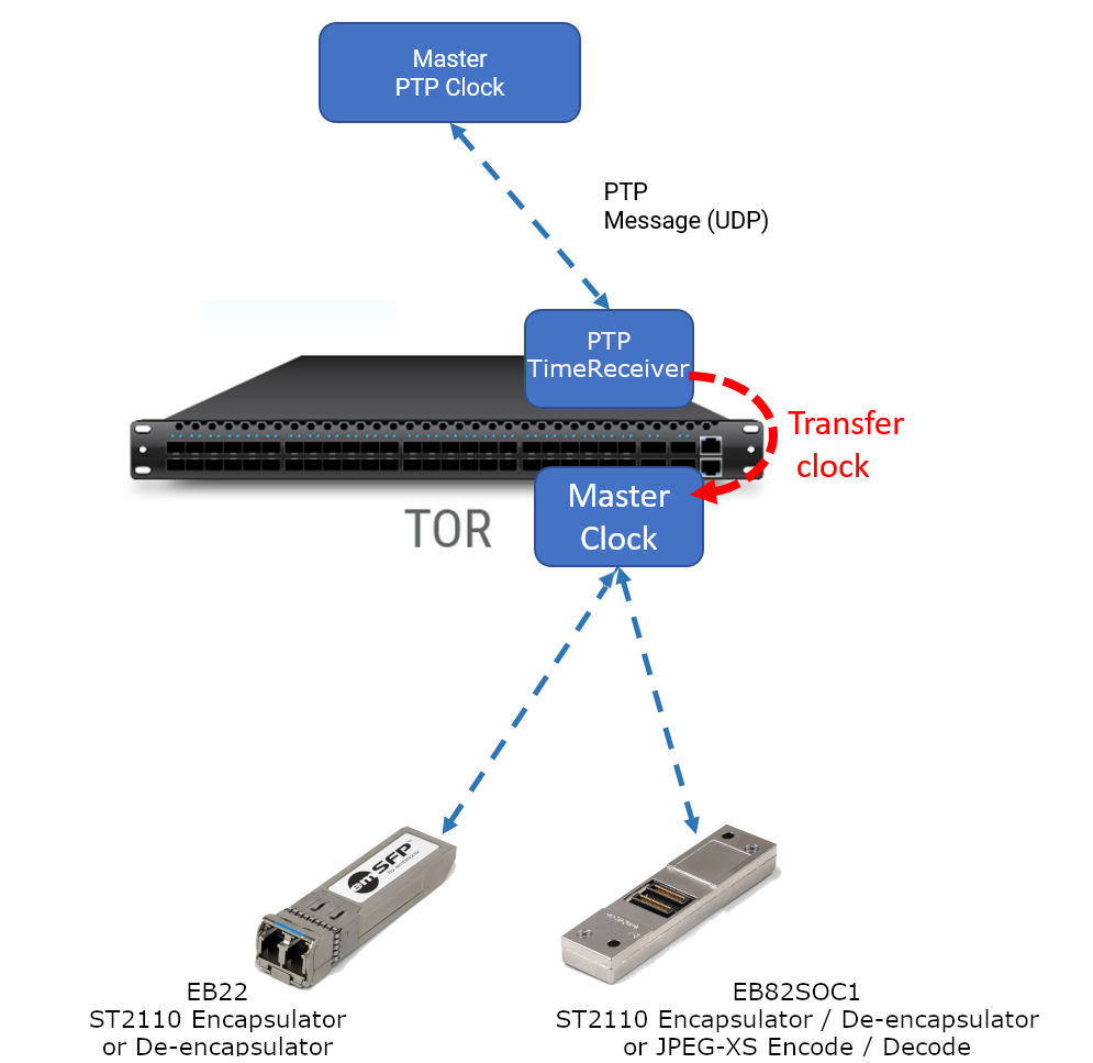
Figure 4. Boundary clock system (courtesy of Michel Proulx)
Once the Time Receiver has iteratively computed its time difference with its Time Transmitter, it is synchronized within sub-microsecond accuracy of UTC. But time synchronization is just the first step. The second step is to use precise time to derive the timing reference signals needed by ST 2110 audio/video devices.
The Society of Motion Picture and Television Engineers (SMPTE) decided to create the ST 2059-1 and ST 2059-2. The ST 2059-1 defined a method of deriving phase aligned audio and video sync from PTP. The ST 2059-2 defined a profile of IEEE-1588 suitable to audio and video requirements.
From the PTP ticks count, Time Receivers accurately find the vertical and the horizontal pulses and align its video to the video reference. It is also possible to extract the audio clocks and finally to generate the Digital Audio Reference (DARS) if required. The following image shows the process of re-creating the clock for synchronization of signals.
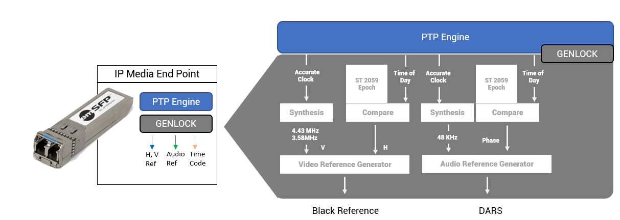
Figure 5. Timing signals generation in IP Media device (courtesy of Michel Proulx)
In an
SDI broadcast environment, timing is crucial. It is no different in an IP broadcast environment; timing is important to synchronize
endpoints. PTP was already used by various industries, so it was an obvious choice to be reused for broadcast.
From our industry’s perspective, PTP is mandatory and therefore is now defined in the ST 2110-10 standard for Audio, Video and Metadata Transport. To be compliant, ST 2110 endpoint (device) should be PTP / ST 2059-1 and ST 2059-2 compliant.
Finally, endpoints such as the emSFP gateways and EB82SOC1 can operate in both transparent clock and boundary clock architectures. However, for improved scalability and accuracy, a boundary clock approach is generally preferred over a transparent clock implementation.
For more information about our products, please contact us at Embrionix_Sales@riedel.net
###
About Embrionix
Embrionix, a subsidiary of Riedel Communications, designs and builds innovative, advanced SMPTE video SFPs to close the gap between fiber optic deployments, coaxial deployments, legacy composite deployments, and emerging technologies, such SDI to IP SFPs. By leveraging its core competencies in video broadcast, the company OEMs highly flexible SFP modules (emSFP) to major manufacturers in the industry. Embrionix headquarters are based in Laval, Quebec. Embrionix sales offices, representatives, and distribution offices are located in Canada, United States, United Kingdom, Germany, France, and Japan.
About Riedel Communications
Riedel Communications designs, manufactures, and distributes pioneering real-time video, audio, data, and communications networks for broadcast, pro audio, event, sports, theater, and security applications. The company also provides rental services for radio and intercom systems, event IT solutions, fiber backbones, and wireless signal transmission systems that scale easily for events of any size, anywhere in the world. Riedel is headquartered in Wuppertal, Germany, and employs over 700 people in 25 locations throughout Europe, Australia, Asia, and the Americas.
All trademarks appearing herein are the property of their respective owners.