1- OverviewThis application note provides a guideline to implement a ‘generic’ pin assignment (pin outs) to support the MSA (Datacom) SFP / MSA (Datacom) SFP+ and non-MSA (Video) SFP and emSFP/emSFP+. This application note focuses on the MSA (Datacom) transceiver and non-MSA (Video) pin outs of the dual receiver, dual transmitter, single receiver, single transmitter and transceiver. When equipment is built by a manufacturer and is intended to interwork with different types of SFPs from different manufacturers the use of an industry standard is critical. To properly inter-operate, the host board and the SFP must support the same electrical levels, mechanical dimensions of the SFP/SFP+ and most importantly, the connector’s pin outs should not create any contention or malfunction. Because the non-MSA (Video) pin outs aren’t standardized, manufacturer should take more precaution before using non-MSA (Video) SFP in a system. MSA (Datacom) pin out is standardized with INF-8074i and SFF-8431for SFP+. In addition to the Embrionix connector pin outs, this application notes also provides a short list of compatible SFPs, contentions solutions and a ‘generic’ one-pin-out-fits-all to help manufacturers use any type of non-MSA (Video) SFP and MSA SFP in the same system.
|
 |
|
|
|
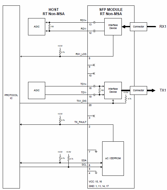
3- Transceiver non-MSA connection with hostThe Figure 1 represents the connection between the host (product) with a non-MSA transceiver SFP available from Embrionix as implemented for professional video solutions.
|
 |
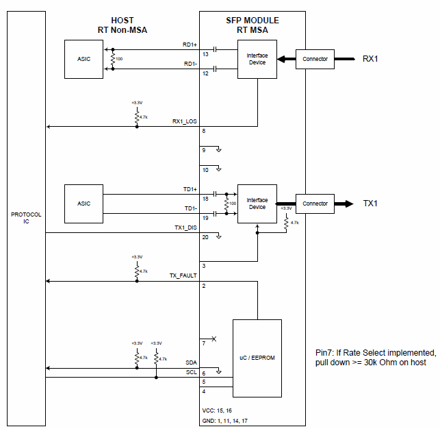
4- Transceiver MSA connection with hostThe Figure 2 represents the connection between the host (product) with a MSA transceiver SFP available from Embrionix and MSA SFP vendor.
|
 |
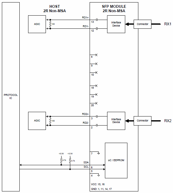
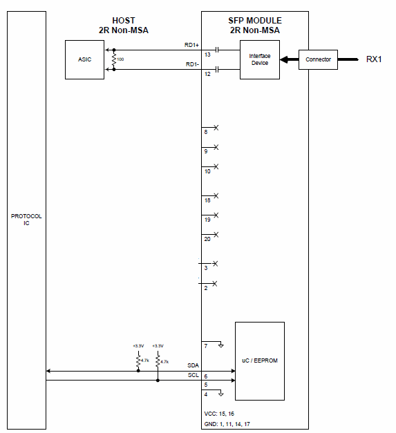
5- Dual receiver connection with hostThe Figure 3 represents the connection between the host (product) and a dual receiver non-MSA SFP, emSFP available from Embrionix as implemented for professional video solutions.
|
 |
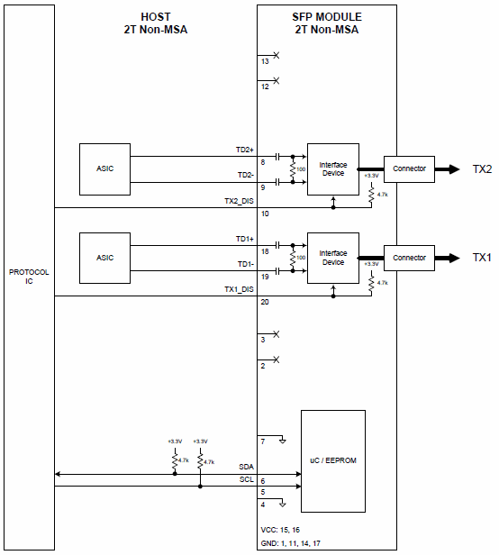
6- Dual transmitter connection with hostThe Figure 4 represents the connection between the host (product) and a dual transmitter non-MSA SFP, emSFP available from Embrionix as implemented for professional video solutions.
|
 |
|
|
 |
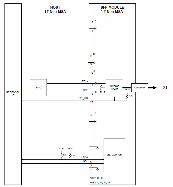
8- Single transmitter connection with hostThe Figure 6 represents the connection between the host (product) and a single transmitter non-MSA SFP, emSFP available from Embrionix as implemented for professional video solutions. MSA pin out is also available, please refer to Figure 2. MSA (Datacom) SFP transceiver connection with Host to adequately connect the MSA single transmitter.
|
 |
|
|
 |
10- Pin#2 problem descriptionFor MSA (Datacom) SFP, the pin 2 represents a TX_FAULT. This pin will be at a 3.3V level when a fault occurs on the Laser, as explain in the MSA SFP document:
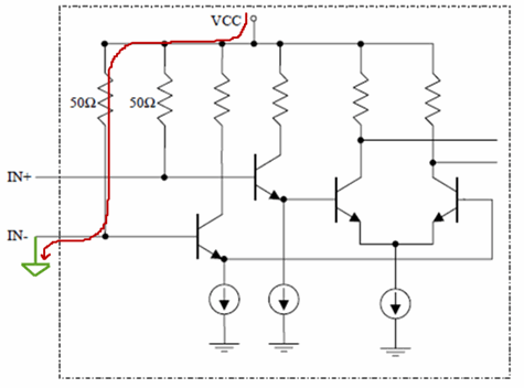
TX Fault is an open collector/drain output, which should be pulled up with a 4.7K – 10KΩ resistor on the host board. Pull up voltage between 2.0V and VccT, R+0.3V. When high, output indicates a laser fault of some kind. Low indicates normal operation. In the low state, the output will be pulled to < 0.8V. The same pin2 in a dual receivers is the differential pair negative input. The high speed deserializer could have two problems with the 3.3V signal. First problem, the pin 2 could create an excessive current consumption if the input CML (or LVPECL, LVDS ) contains termination (in IC or onboard). The following picture shows the CML input current to ground. Second problem, the pin 2 on the receiving device may be powered up with a different voltage than 3.3V. High speed serializer and deserializer (serdes) contain in semiconductor could be supplied with a 1.2V, 1.8V, 2.5V, in this case, the 3.3V can damage the serdes. A normal SFP module should be open drain so there will not be any problem with this connection, but the pull up resistor on the host board, will connect the 3.3V to the serdes IO. |
 |
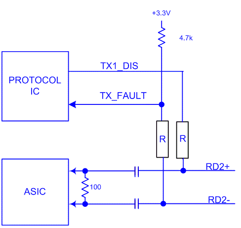
11- Pin#2 solutionThe easiest solution is to add AC-coupling capacitor (recommended value 4.7uF) between the SFP connector and the IC, but the pull up should be placed on the SFP side. The pin 3 should also have an AC-coupling capacitor, ideally located at the same place between the SFP connector and the IC, to ensure that the trace has the same discontinuity (pin#3 problem will be addressed in the following section). Finally, an RF choke (1K ohm resistor) should be placed on the signal as close as possible to the SFP connector. This ensures that no high frequency stub will be seen by the receiving device. The differential pairs for SFP+, emSFP+ should be carefully designed to pass the return loss specification of the host and more importantly the signal should be as good as possible to allow the serdes to recover the signal.
|
 |
12- Pin#3 problem descriptionFor MSA (Datacom) SFP, the pin 2 represents a TX_DIS. This pin will be at a 3.3V level when the host disables the laser, as explained in the MSA SFP document:
TX disable is an input that is used to shut down the transmitter optical output. It is pulled up within the module with a 4.7 – 10 KΩ resistor. Its states are: Low (0 – 0.8V): Transmitter on (>0.8, < 2.0V): Undefined High (2.0 – 3.465V) : Transmitter Disabled Transmitter Disabled Open: Transmitter Disabled The pin3 in a dual receivers is the differential pairs positive input. The high speed deserializer could have two problems with the 3.3V signal like the pin 2. |
|
13- Pin#3 solutionThe easiest solution is to follow the same recommendation as for the pin#2.
|
|
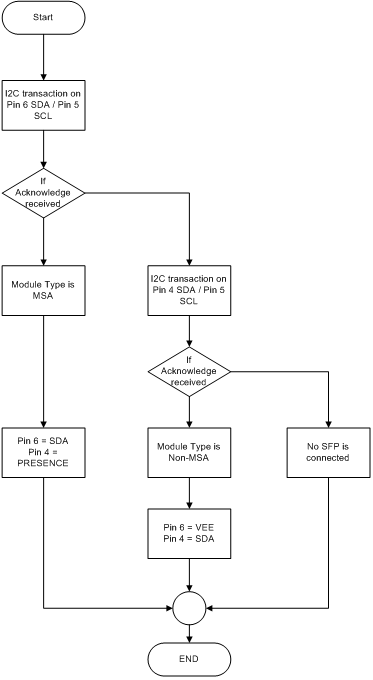
14- Pin#4 &6 problem descriptionThe MSA MOD_DEF(2) is the I2C SDA communication line, the equivalent IO for a non-MSA module is the pin 6. When the protocol IC communicates, it sends the clock and the data on those pins to retrieve data and control the SFP, emSFP, SFP+ and emSFP+. The following table shows the pin out of the MSA (Datacom) SFP and the non-MSA (video) SFP.
|
|
|
|
 |
16- Pin#8 problem descriptionThe pin 8 problem is similar to pin 2 and 3 problems. The pin should be connected to the semiconductor high speed output pin (CML, LVPECL, LVDS, etc…) in the case of the dual transmitters and to a logic level (LVCMOS, LVTTL) in the case of a dual receivers. The RX1_LOS could be obtained by the I2C interface in the Embrionix dual receivers SFP, the pin RX1_LOS is identical to the register 110 bit 1. The RX1_LOS as defined in the SFP multi source agreement is open drain and the pull-up resistor should be placed on the host.
|
|
17- Pin#9 problem descriptionThe pin 9 should be AC coupled to keep the Tx2 pair balanced. The pin should be connected to the semiconductor high speed output pin (CML, LVPECL, LVDS, etc…) in the case of the dual transmitters and to a ground VEE in the case of a MSA transceiver.
|
|
18- Pin#9 SolutionAgain, the easiest solution is to add AC-coupling capacitor (recommended value 4.7uF) between the SFP connector and the IC to keep the pair balanced.
|
|
19- Pin#10 problem descriptionThe pin 10 is a ground VEE for the MSA transceiver and the Tx2_DIS for the non-MSA.
|
|
20- Pin#10 SolutionBy detecting the type of SFP, MSA (Datacom) or non-MSA (video), the protocol IC should not drive this pin to a high level. If the host follows the multisource agreement this IO is open drain on the host and the host can only drive a low level. The low level should be equivalent to the VEE of the MSA SFP. This will prevent any problem on this IO. No special care required on pin 10.
|
|
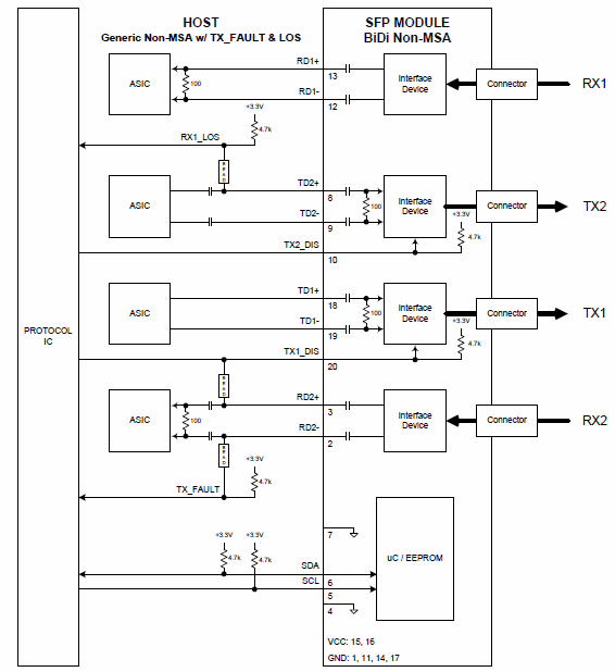
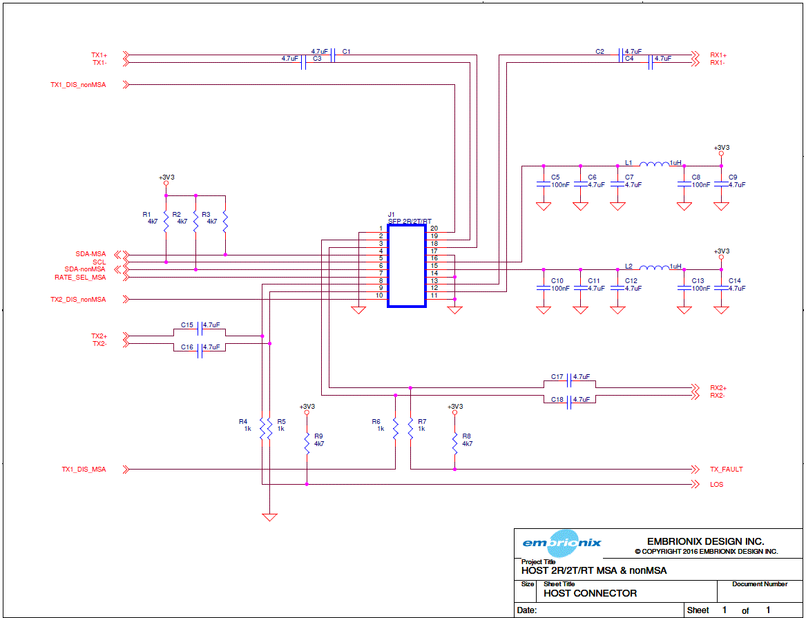
21- Final generic pin outsThe following schematic represents the generic pin out to inter-operate with the dual transmitters, dual receivers and Non-MSA (Video) transceiver.
|
 |
###
About Embrionix
Embrionix, a subsidiary of Riedel Communications, designs and builds innovative, advanced SMPTE video SFPs to close the gap between fiber optic deployments, coaxial deployments, legacy composite deployments, and emerging technologies, such SDI to IP SFPs. By leveraging its core competencies in video broadcast, the company OEMs highly flexible SFP modules (emSFP) to major manufacturers in the industry. Embrionix headquarters are based in Laval, Quebec. Embrionix sales offices, representatives, and distribution offices are located in Canada, United States, United Kingdom, Germany, France, and Japan.
About Riedel Communications
Riedel Communications designs, manufactures, and distributes pioneering real-time video, audio, data, and communications networks for broadcast, pro audio, event, sports, theater, and security applications. The company also provides rental services for radio and intercom systems, event IT solutions, fiber backbones, and wireless signal transmission systems that scale easily for events of any size, anywhere in the world. Riedel is headquartered in Wuppertal, Germany, and employs over 700 people in 25 locations throughout Europe, Australia, Asia, and the Americas.
All trademarks appearing herein are the property of their respective owners.